Thursday 8 November 2012

WEEK 14 FYP 2


Title:
Viva/Presentation Day/Industry Day

Objective:
To present FYP final output to assessors

Content/Result:
I'm able to present my final output for FYP 2 to assessors which is Sir Saiful Yusri and Sir Shamsul Adlan, both from communication section. Below are my poster


Conclusion:
I've completed my final presentation for FYP 2. I need to submit the draft of FYP report to my advisor; Madam Lily on week 15. And the full report need to be submit on week 17


Thursday 1 November 2012

WEEK 13 FYP 2


Title:
Complete Program for LSB, Masking/Filtering and DCT

Objective:
To combine and finalize all of the method into full program

Content/Result:
I combined all of the method into a full/complete program with GUI

Front Page GUI

Method 1 LSB GUI

Method 2 Masking/Filtering GUI

Method 3 DCT GUI


Conclusion:
All of the method is functioning and successfully combined together in the full program GUI


Friday 26 October 2012

WEEK 12 FYP 2


Title:
Combining method 3 coding with GUI

Objective:
To combine and finalize the coding and GUI for Method 2: Discrete Cosine Transformation

Content/Result:
After I completing the coding process and GUI, now I combined it together to show the output which contains the original image and the stego image by using Discrete Cosine Transformation method. Below is the full programmed for Discrete Cosine Transformation method. The "Ninja Turtle" image is the original image. The "Boy" is the secret image that need to be hide. When the "Ninja Turtle" is embedded, its contains the secret image in it.


Conclusion:
After applying the coding, the changes at the low frequencies (top left corner) of the cover image is a little obvious. This is because I focuses and hide the hidden image in the low frequencies and ignoring the high frequencies of it. Although it is obvious, somehow human visible vision did not aware of the changes.


Friday 19 October 2012

WEEK 11 FYP 2


Title:
Built Graphic User Interface (GUI)

Objective:
To create Graphic User Interface (GUI) for MATLAB coding

Content/Result:
I built GUI that will be use together with coding from last week. Below is the GUI for DCT method. To run the GUI, user needs to:
  1. Select the cover image
  2. Select the secret image
  3. Press hide the image button
  4. Save the embedded image
  5. Press recover image button to recover image


Conclusion:
This GUI will be used as my Interface together with the Discrete Cosine Transformation coding. User can see the original image and the hidden image before and after the stego process.


Friday 12 October 2012

WEEK 10 FYP 2


Title:
Discrete Cosine Transformation Source Code

Objective:
To gain and generate the coding for Image Steganography by using Discrete Cosine Transformation method

Content/Result:
For Discrete Cosine Transformation, I used the DCT formula built-in in the MATLAB. The steps that I've done are:
  1. read the cover image
  2. broke the cover image into 8×8 block of pixels (segmentisation)
  3. applied the DCT function for each block of cover image
  4. read the hidden image
  5. applied the DCT function for f hidden image
  6. merge/hide the DCT cover image and the DCT hidden image
  7. applied inverse DCT function for the merged image of cover and hidden image

Some of the coding examples is as below:

% RED
for i=1:100
    for j=1:100
        blockmatrix = CoverR( (i-1)*8+1:(i-1)*8+8, (j-1)*8+1:(j-1)*8+8 );
        dctblockmatrix = dct(blockmatrix);
        JEmbedR( (i-1)*8+1:(i-1)*8+8, (j-1)*8+1:(j-1)*8+8 ) = dctblockmatrix;
        JEmbedR( (i-1)*8+8:(i-1)*8+8, (j-1)*8+8:(j-1)*8+8 ) = JHiddenR(i, j);
    end
end
for i=1:100
    for j=1:100
        blockmatrix = JEmbedR( (i-1)*8+1:(i-1)*8+8, (j-1)*8+1:(j-1)*8+8 );
        invdctblockmatrix = idct(blockmatrix);
        uncoverR( (i-1)*8+1:(i-1)*8+8, (j-1)*8+1:(j-1)*8+8 ) = invdctblockmatrix;
    end
end


Conclusion:
The DCT method can separate the image into low, medium and high frequencies. Most of the data are stored in low frequencies. So the hidden image will be store in low frequencies.


Friday 5 October 2012

WEEK 9 FYP 2


Title:
Research for Discrete Cosine Transformation (DCT)

Objective:
To know deeply about Discrete Cosine Transformation (DCT) method used in Image Steganography

Content/Result:
  • The DCT transforms a signal or image from the spatial domain to the frequency domain. 
  • It separates the image into parts (or spectral sub-bands) of differing importance (with respect to the image's visual quality). 
  • It can separate the image into High, Middle and Low Frequency components. 
  • The human eye is able to catch modifications to the lower frequencies since most of the image's frequency content is located in this area.  
  • For each color component, the JPEG image format uses a discrete cosine transform (DCT) to transform successive 8 × 8 pixel blocks of the image into 64 DCT coefficients each. The DCT coefficients F(u, v) of an 8 × 8 block of image pixels f(x, y) are given by 

DCT 8x8 basic function

             
Original image before DCT applied
Original image after DCT applied

Conclusion:
The JPEG image format uses a discrete cosine transform (DCT) to transform successive 8 × 8 pixel blocks of the image into 64 DCT coefficients each. It can separate the image into High, Middle and Low Frequency components. The human eye is able to catch modifications to the lower frequencies since most of the image's frequency content is located in this area. 


Friday 28 September 2012

WEEK 8 FYP 2


Title:
Combining method 2 coding with GUI

Objective:
To combine and finalize the coding and GUI for Method 2: Masking and Filtering

Content/Result:
After I completing the coding process and GUI, now I combined it together to show the output which contains the original image and the stego image by using Masking and Filtering method. Below is the full programmed for Masking and Filtering method. The "Michael Jackson" image is the original image. The "Pirates" is the secret image that need to be hide. When the "Michael Jackson" is embedded, its contains the secret image in it.


Conclusion:
After applying the coding, the luminance of the cover image; "Michael Jackson" is slightly different. However he differences between those two image is cannot slightly detected by human visual system.


Friday 14 September 2012

WEEK 7 FYP 2


Title:
Built Graphic User Interface (GUI)

Objective:
To create Graphic User Interface (GUI) for MATLAB coding

Content/Result:
I built GUI that will be use together with coding from last week. Below is the GUI for LSB method. To run the GUI, user needs to:
  1. Select the cover image
  2. Select the secret image
  3. Press hide the image button
  4. Save the embedded image
  5. Press recover image button to recover image


Conclusion:
This GUI will be used as my Interface together with the Masking and Filtering coding. User can see the original image and the hidden image before and after the stego process.


Friday 7 September 2012

WEEK 6 FYP 2


Title:
Masking and Filtering Source Code

Objective:
To gain and generate the coding for Image Steganography by using Masking and Filtering method

Content/Result:
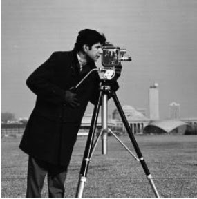
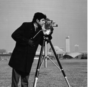
For masking and filtering, I changed the luminance of the cover image by inserting the hidden image in it. The steps that I've done are:
  1. read the cover and hidden image
  2. cover the cover image into binary matrix
  3. hide the hidden image into the matrix of cover matrix
  4. update the binary matrix of the cover image
  5. convert back the update binary matrix of cover + hidden into numerical
  6. extract the hidden image
  7. update the binary matrix of the cover image
Some of the coding examples is as below:

function [I_image_rev] = mf_image(coverimg, hiddenimg)


%% read the cover and hidden images
I_image = coverimg;
I_hidden = hiddenimg;
[m,n,o]=size(I_image);
[m1,n1] = size(I_hidden);

%% cover the cover image into binary matrix
for i=1:m,
    for j=1:n,
        for k=1:o,
            I_image_bin{i,j,k} = {dec2bin(I_image(i,j,k),8)};
        end
    end
end

%% hide the hidden image into the matrix of cover matrix
for i=1:m1,
    for j=1:n1,
            I_image_hidden{i,j} = {dec2bin(I_hidden(i,j),8)};
            
            binaryof_I_image_hidden = cell2mat(I_image_hidden{i,j});
            
            binaryof_I_image_bin_1st_R = cell2mat(I_image_bin{(i-1)*3+1,j,1});
            binaryof_I_image_bin_1st_G = cell2mat(I_image_bin{(i-1)*3+1,j,2});
            binaryof_I_image_bin_1st_B = cell2mat(I_image_bin{(i-1)*3+1,j,3});
            binaryof_I_image_bin_2nd_R = cell2mat(I_image_bin{(i-1)*3+2,j,1});
            binaryof_I_image_bin_2nd_G = cell2mat(I_image_bin{(i-1)*3+2,j,2});
            binaryof_I_image_bin_2nd_B = cell2mat(I_image_bin{(i-1)*3+2,j,3});
            binaryof_I_image_bin_3rd_R = cell2mat(I_image_bin{(i-1)*3+3,j,1});
            binaryof_I_image_bin_3rd_G = cell2mat(I_image_bin{(i-1)*3+3,j,2});
            binaryof_I_image_bin_3rd_B = cell2mat(I_image_bin{(i-1)*3+3,j,3});


Conclusion:
I hide the secret image by changing the luminance of the cover image. The differences between those two image is cannot slightly detected by human visual system.


Friday 31 August 2012

WEEK 5 FYP 2


Title:
Research for Masking and Filtering

Objective:
To know deeply about Masking and Filtering method used in Image Steganography

Content/Result:
  • Masking and filtering techniques are mostly used on 24 bit and greyscale images. They hide info in a way similar to watermarks on actual paper and are sometimes used as digital watermarks. 
  • Masking images entails changing the luminance of the masked area. The smaller the luminance change, the less of a chance it can be detected. Because watermarking techniques are more integrated into the image,they may be applied without fear of image destruction from lossy compression. 
  • By covering, or masking a faint but perceptible signal with another to make the first non-perceptible, it exploit the fact that the human visual system cannot detect slight changes in certain temporal domains of the image.
  • Masking techniques are more suitable for use in lossy JPEG images than LSB insertion because of their relative immunity to image operations such as compression cropping. Stego-images that are masked will keep a higher fidelity than LSB through compression, cropping and some image processing. The reason that a stego image encoded with masking, degrades less under JPEG compression is that the secret message is hid in the significant areas of the picture.
The left image is the original image. The right image is image after masking and filtering technique applied

Conclusion:
Masking does change the visible properties of an image, it can be done in such a way that the human eye will not notice the anomalies. It is more robust than LSB modification with respect to compression, cropping and different kinds of image processing. The information is hidden inside the visible part of the image, which makes it more suitable than LSB modifications in case a lossy compression algorithm like JPEG is being used.


Friday 24 August 2012

WEEK 4 FYP 2


Title:
Combining the coding with GUI

Objective:
To combine and finalize the coding and GUI for Method 1: LSB

Content/Result:
After I completing the coding process and GUI, now I will combine it together to show the output which contains the original image and the stego image by using LSB method. Below is the full programmed for LSB method. The "Michael Jackson" image is the original image. The "Pirates" is the secret image that need to be hide. When the "Michael Jackson" is embedded, its contains the secret image in it.


Conclusion:
LSB method is successfully works. The embedded image size is bigger than the original image because it's contain a secret message in it. The hidden message must be smaller than the original image. The embedded image is saved in Bitmap because it is lossless.


Friday 17 August 2012

WEEK 3 FYP 2


Title:
Built Graphic User Interface (GUI)

Objective:
To create Graphic User Interface (GUI) for MATLAB coding

Content/Result:
I built GUI that will be use together with coding from last week. Below is the GUI for LSB method. To run the GUI, user needs to:
  1. Select the cover image
  2. Select the secret image
  3. Press hide the image button
  4. Save the embedded image
  5. Press recover image button to recover image


Conclusion:
This GUI will be used as my Interface together with the LSB coding. User can see the original image and the hidden image before and after the stego process.


Friday 10 August 2012

WEEK 2 FYP 2


Title:
Least Significant Bit Source Code

Objective:
To gain and generate the coding for Image Steganography by using LSB method

Content/Result:
For method 1, I inserted the binary number of hidden image into the binary number of cover image. And the embedded image is saved with Bitmap format. The step involved in LSB coding is:

  1. read the cover and hidden image
  2. cover the cover image into binary matrix
  3. hide the hidden image into the matrix of cover matrix
  4. update the binary matrix of the cover image
  5. convert back the update binary matrix of cover + hidden into numerical
  6. extract the hidden image
  7. update the binary matrix of the cover image

Some of the coding examples is as below:

 function [I_image_rev] = lsb_image(coverimg, hiddenimg)

%% read the cover and hidden images
I_image = coverimg;
I_hidden = hiddenimg;
[m,n,o]=size(I_image);
[m1,n1] = size(I_hidden);

%% cover the cover image into binary matrix
for i=1:m,
    for j=1:n,
        for k=1:o,
            I_image_bin{i,j,k} = {dec2bin(I_image(i,j,k),8)};
        end
    end
end

%% hide the hidden image into the matrix of cover matrix
for i=1:m1,
    for j=1:n1,
            I_image_hidden{i,j} = {dec2bin(I_hidden(i,j),8)};
            
            binaryof_I_image_hidden = cell2mat(I_image_hidden{i,j});
            
            binaryof_I_image_bin_1st_R = cell2mat(I_image_bin{(i-1)*3+1,j,1});
            binaryof_I_image_bin_1st_G = cell2mat(I_image_bin{(i-1)*3+1,j,2});
            binaryof_I_image_bin_1st_B = cell2mat(I_image_bin{(i-1)*3+1,j,3});
            binaryof_I_image_bin_2nd_R = cell2mat(I_image_bin{(i-1)*3+2,j,1});
            binaryof_I_image_bin_2nd_G = cell2mat(I_image_bin{(i-1)*3+2,j,2});
            binaryof_I_image_bin_2nd_B = cell2mat(I_image_bin{(i-1)*3+2,j,3});
            binaryof_I_image_bin_3rd_R = cell2mat(I_image_bin{(i-1)*3+3,j,1});
            binaryof_I_image_bin_3rd_G = cell2mat(I_image_bin{(i-1)*3+3,j,2});
            binaryof_I_image_bin_3rd_B = cell2mat(I_image_bin{(i-1)*3+3,j,3});


Conclusion:
For this method, the 8th bit of each byte of the image is changed to the bit of secret message. For 24 bit image, the colours of each component like RGB (red, green and blue) are changed.


Friday 3 August 2012

WEEK 1 FYP 2


Title:
Research for Least Significant Bit (LSB)

Objective:
To know deeply about Least Significant Bit (LSB) used in Image Steganography

Content/Result:
  • LSB (Least Significant Bit) substitution is the process of adjusting the least significant bit pixels of the carrier image. It is a simple approach for embedding message in to the image. The Least Significant Bit insertion varies according to number of bits in an image. For an 8 bit image, the least significant bit; in example; the 8th bit of each byte of the image is changed to the bit of secret message. For 24 bit image, the colours of each component like RGB (red, green and blue) are changed. LSB is effective in using BMP images since the compression in BMP is lossless. But for hiding the secret message inside an image of BMP file using LSB algorithm it requires a large image which is used as a cover. 
  • LSB substitution is also possible for GIF formats, but the problem with the GIF image is whenever the least significant bit is changed the whole colour palette will be changed. The problem can be avoided by only using the gray scale GIF images since the gray scale image contains 256 shades and the changes will be done gradually so that it will be very hard to detect. For JPEG, the direct substitution of steganographic techniques is not possible since it will use lossy compression. So it uses LSB substitution for embedding the data into images. 
  • For example, the following grid can be considered as 3 pixels of a 24-bit color image, using 9 bytes of memory: 
                                               (00100111 11101001 11001000)

                                               (00100111 11001000 11101001)

                                               (11001000 00100111 11101001)

When the other image, which binary value equals 10000001, is inserted, the following grid results:

                                              (00100111 11101000 11001000)

                                              (00100110 11001000 11101000)

                                              (11001000 00100111 11101001)


Left is the Original Image. Right is the image after LSB substitution


Conclusion:
LSB is the process of adjusting the least significant bit pixels of the carrier image. It is a simple approach for embedding message intothe image. The Least Significant Bit insertion varies according to number of bits in an image. LSB is effective in using BMP images since the compression in BMP is lossless


Friday 27 April 2012

WEEK 14 FYP 1


Title:
Submission of Project Proposal, Progress Report and Draft for Final Report

Objective:
To submit Project Proposal, Progress Report and Draft for Final Report

Content/Result:
Project Proposal will be carry 10% and Progress Report will be carry 5% of marks for FYP Semester 2

Conclusion:
I've submitted the Project Proposal, Progress Report and Draft for Final Report to Madam Lily


Friday 20 April 2012

WEEK 13 FYP 1


Title:
Proposal, Progress Report and Draft

Objective:
To complete the Proposal, Progress Report and Draft for FYP 1 Semester 1

Content/Result:
I've complete all the documantations for FYP Semester 1. The documentations needs is proposal, progress report and draft for final report (Chapter 1, Chapter 2 and Chapter 3)

Conclusion:
I've completed all FYP Semester 1 documentations as Madam Lily want her advisee to submit all of the documentations together in Week 14.


Friday 13 April 2012

WEEK 12 FYP 1


Title:
FYP 1 Presentation

Objective:
To present all research and works that have been done for FYP Semester 1 to assessors.

Content/Result:
Below are my slide show during the presentation


Conclusion:
The VIVA was assess by other lecturer. Marks allocated for this VIVA will be carry forward to FYP Semester 2.